Technical specifications
Power supply: 230V AC ~ 50Hz
Switching capabilities: 230V AC – 10A // 30V DC – 10A
Consumption: <1W
Maximum output power: 2300W (Resistive load)
Frequency range: 868,0 to 868,6 Mhz
Maximum radio power: +3dBm
Radio range – inside use:
Masonry: 30m
Reinforced concrete: 15m
Placoplatre or wood: 40m
Operational temperature: 0°C to 40°
Protection index: IP 2X
Pairing: up to 22 controllers
EEP (Profil EnOcean): D2-01-0F
Dimension: 40 mm (l) x 44 mm (L) x 16.9 mm (h)
Installation
Wiring diagrams
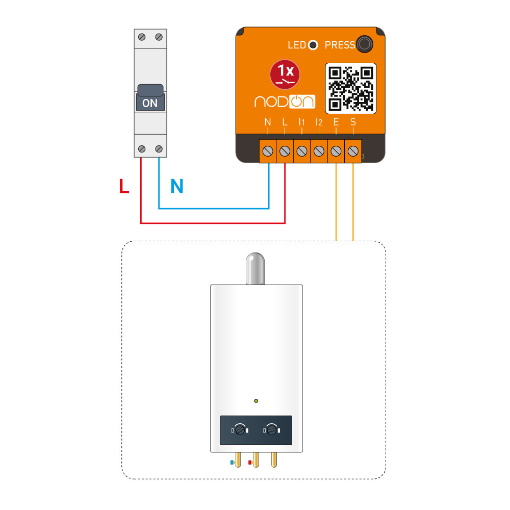
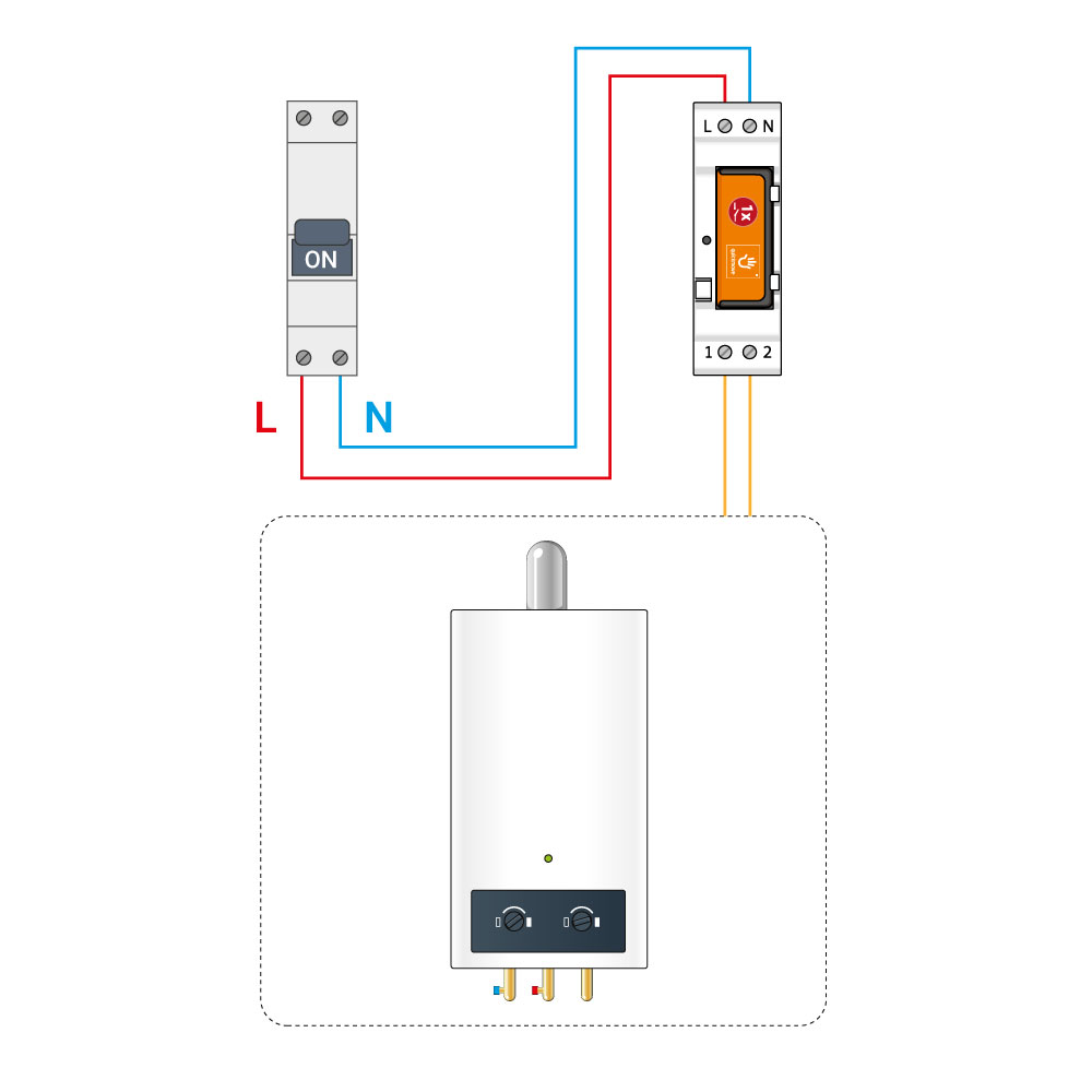
On a boiler
Installation at the electrical panel – NodOn DIN Rail Box is needed
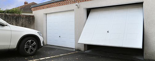
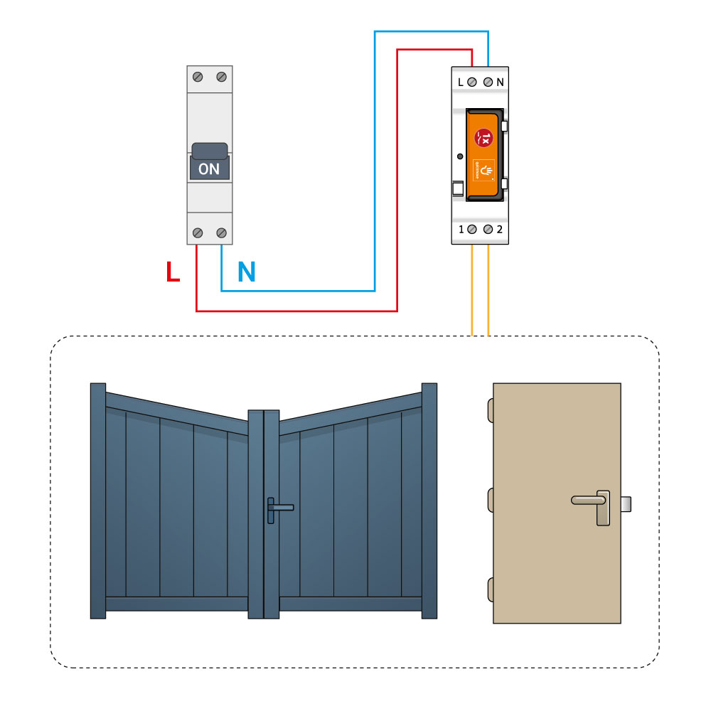
On a garage door, a gate or an electric door-opener
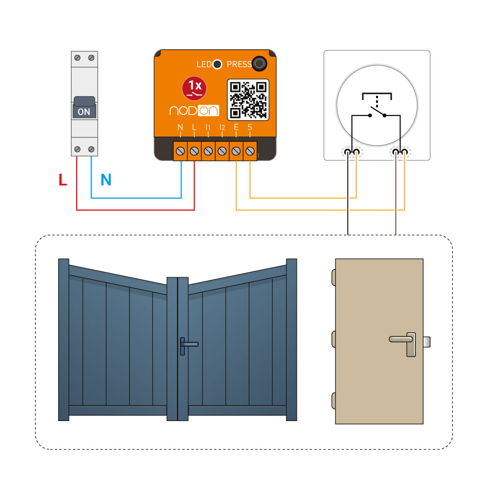
Installation at the electrical panel – NodOn DIN Rail Box is needed
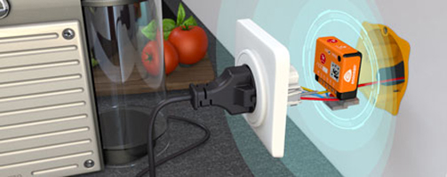
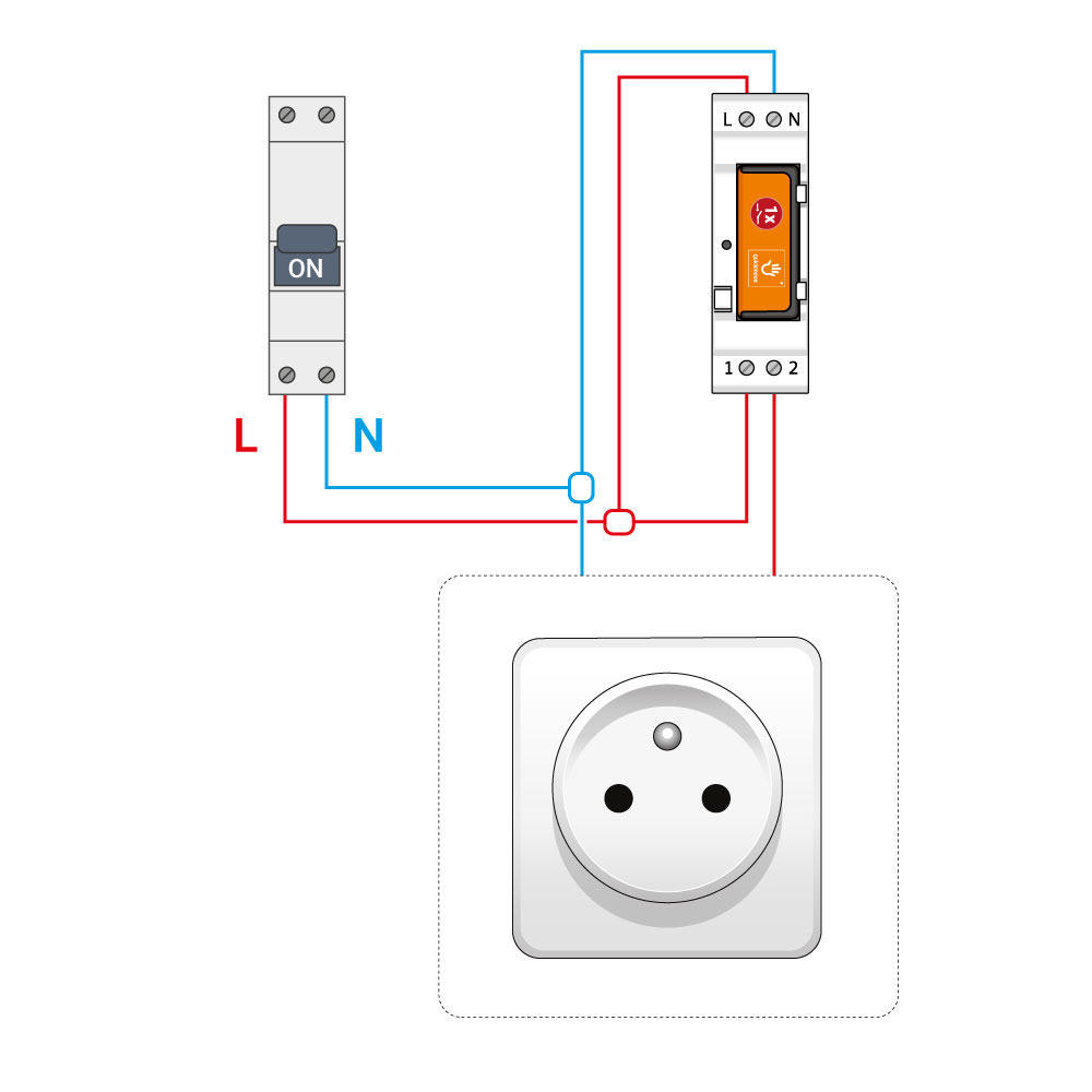
On a wall plug
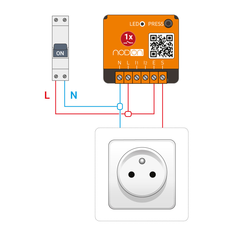
Installation at the electrical panel – DIN Rail Box is needed
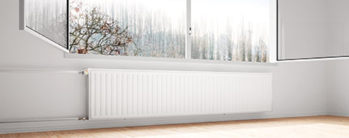
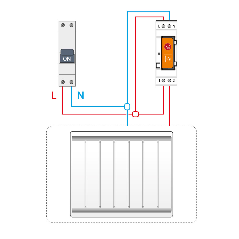
On an electrical heater
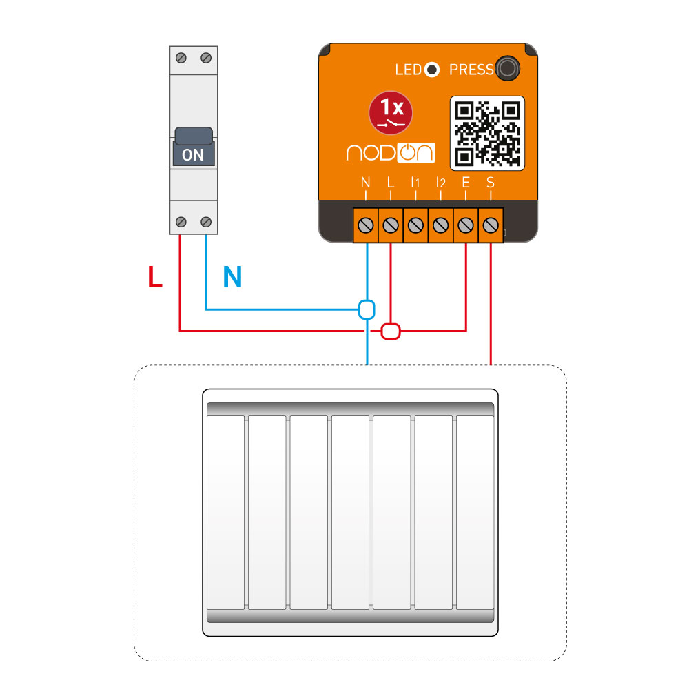
Installation at the electrical panel – NodOn DIN Rail Box is needed
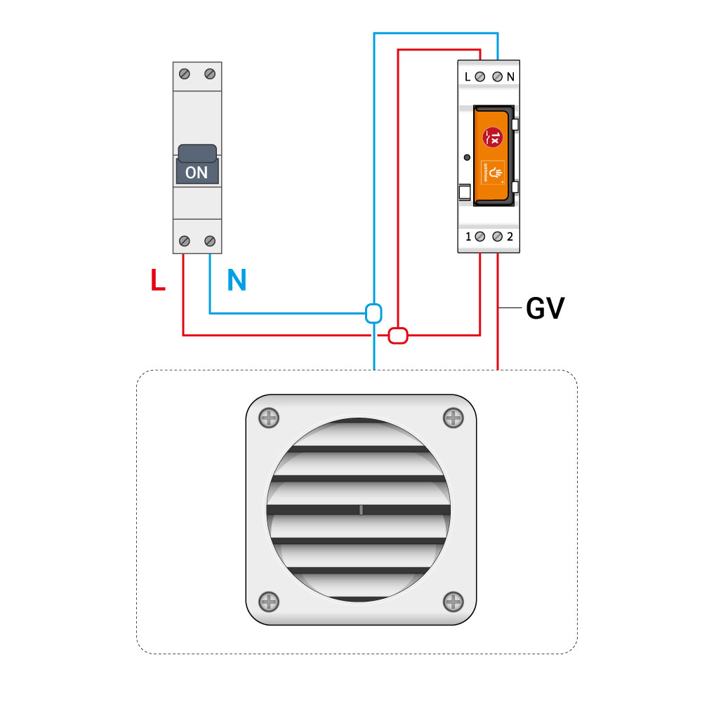
On a CMV
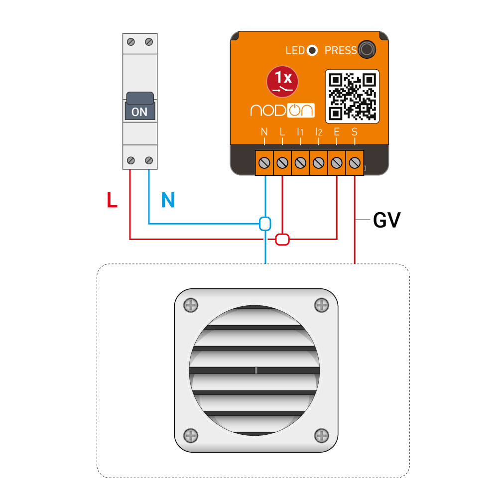
Installation at the electrical panel – NodOn DIN Rail Box is needed
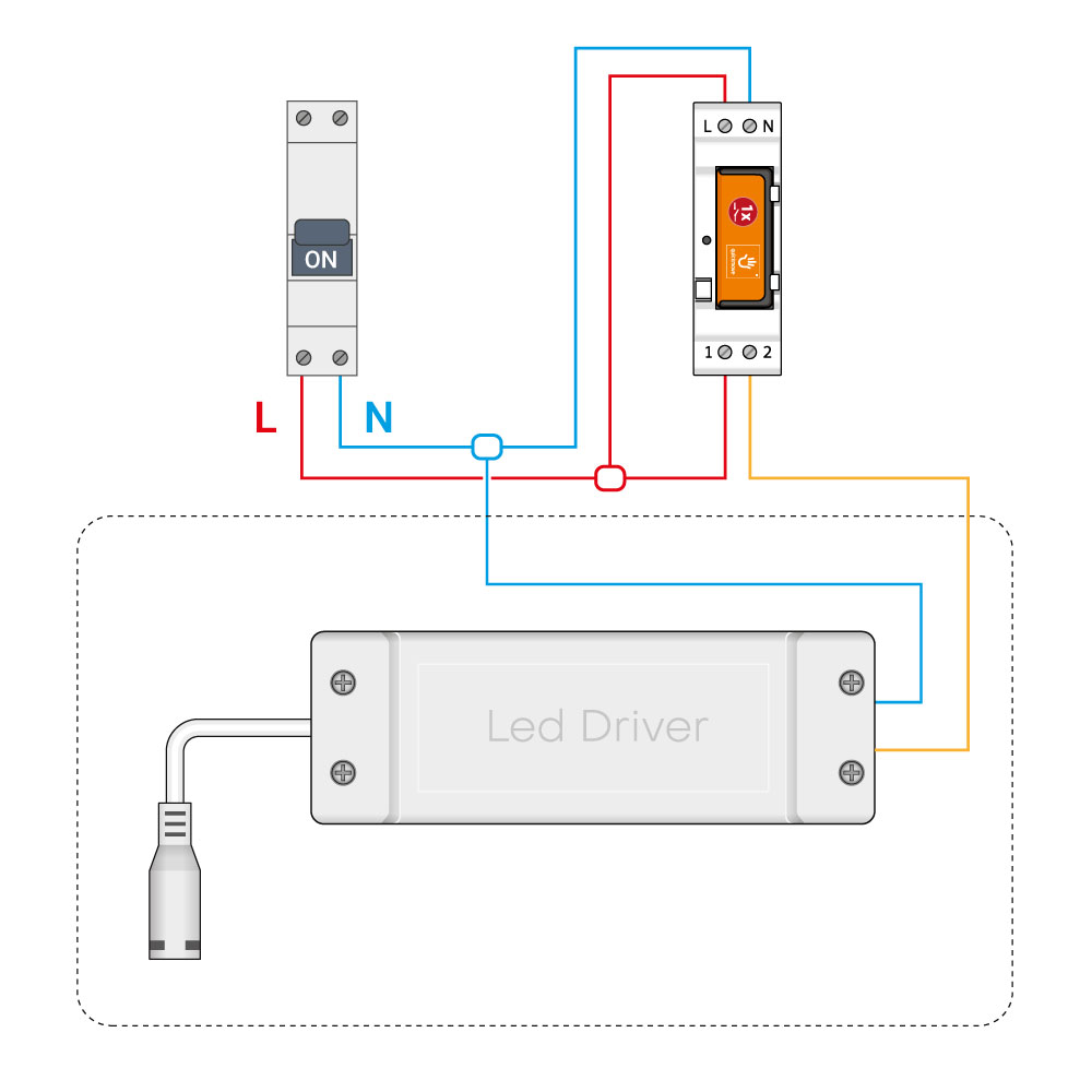
On a LED driver
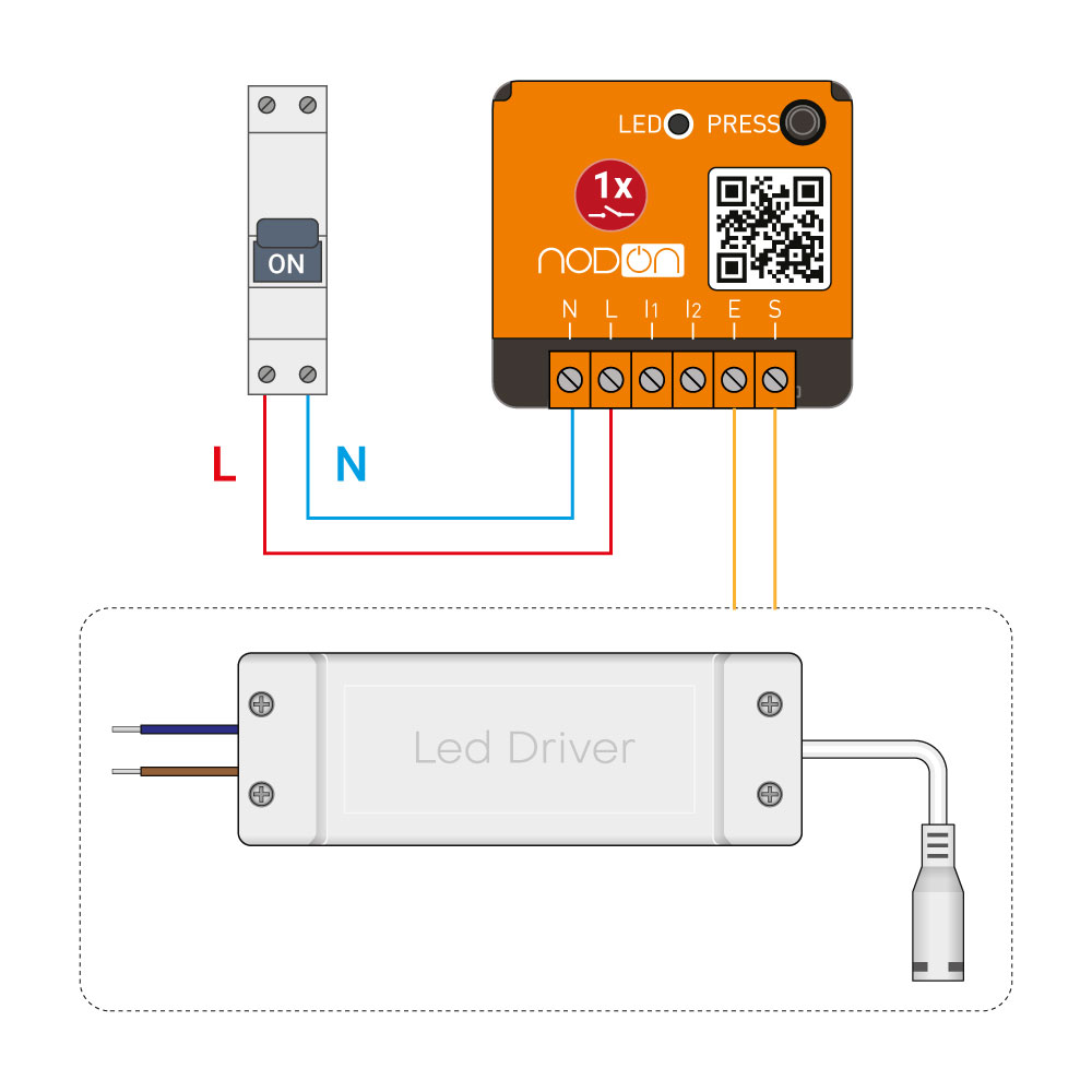
Installation at the electrical panel – NodOn DIN Rail Box is needed
Pairing procedures
Pairing with a wall switch, a remote (EEP: F6-02-01)

Please refer to the Multifunction Relay Switch user guide.
Pairing with a card switch (EEP: F6-04-01)
1 – Put the Multifunction Relay Switch in « Pairing mode ». Activate the control access mode if you want to use the card switch with a gate/garage door/electric latch (see the user guide),
2 – You have 30 seconds to insert or remove the card from the reader. The movement of the card done during the pairing process is the movement which will switch ON the relay switch. The opposite movement will switch OFF the relay switch.
3 – To initialize the Multifunction Relay Switch, insert and remove (or remove and insert) the card.

To unpair this controller:
1 – Put the Multifunction Relay Switch in « Pairing mode ».
2 – Insert or remove the card. The controller can’t control the Multifunction Relay Switch anymore.
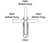
Pairing with a window handle (EEP: F6-10-00)
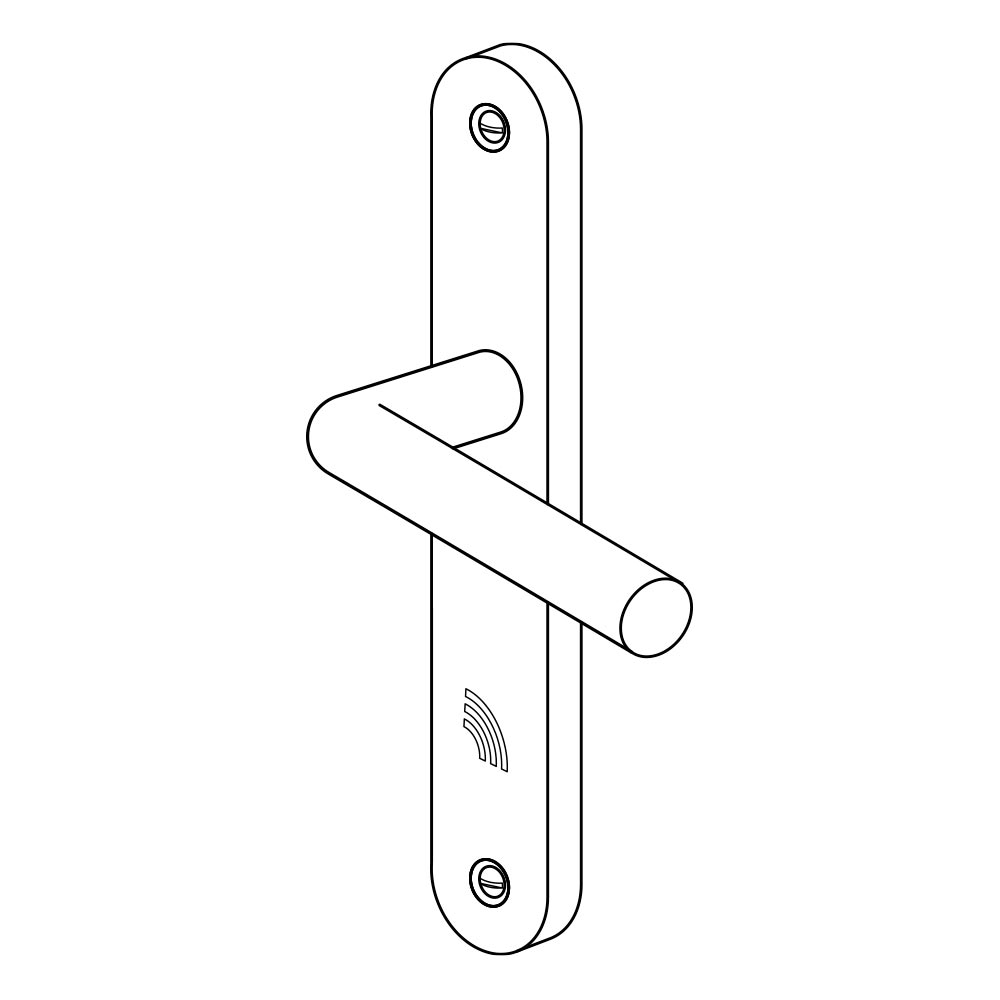
1 – Put the Multifunction Relay Switch in « Pairing mode ».
2 – Make the relevant movement with the handle according to your need. Check below table.
Note: “Bottom hung” and “Open” position are identically considered.

To unpair this controller:
1 – Put the Multifunction Relay Switch in « Pairing mode ».
2 – Make any kind of movement with the handle. The controller can’t control the Multifunction Relay Switch anymore.
Pairing with an opening sensor (EEP: D5-00-01)
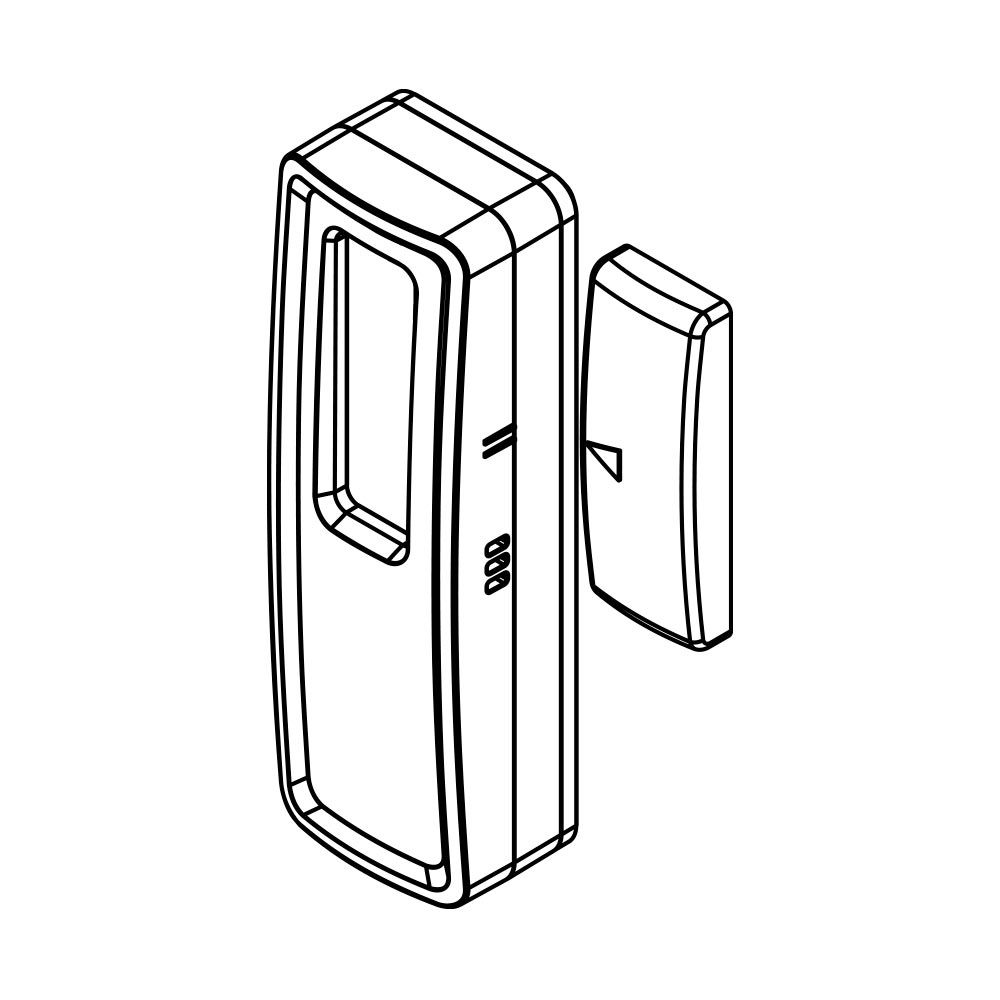
1 – Put the Multifunction Relay Switch in « Pairing mode ».
2 – Press on the « learning » button of the opening sensor. The position (close or far) of the magnet from the sensor when the « learning » button is pressed is the position which will switch ON the Multifunction Relay Switch. The opposite position will switch OFF the Multifunction Relay Switch. Check the table below.
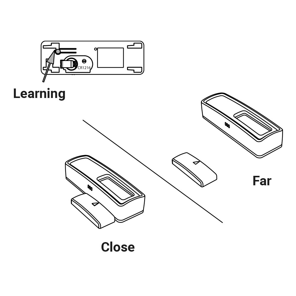

To unpair this controller:
1 – Put the Multifunction Relay Switch in « Pairing mode ».
2 – Press on the « learning » button. The controller can’t control the selected channel of the Multifunction Relay Switch anymore.
Pairing with a motion sensor (EEP: A5-07-01 / A5-07-02 / A5-07-03 / A5-08-01 / A5-08-02 / A5-08-03)
1 – The status of the Multifunction Relay Switch (ON or OFF) chose before put in « Pairing mode » will be associated to a presence detection.
2 – Put the Multifunction Relay Switch in « Pairing mode ». Select the channel you want to pair.
3 – Press on the « learning » button of the opening sensor. When a presence is detected, the Multifunction Relay Switch will be in the state (ON or OFF) defined at step 1. When no presence is detected, the Multifunction Relay Switch will be in the opposite state.
Check the table below.

To unpair this controller:
1 – Put the Multifunction Relay Switch in « Pairing mode ».
2 – Press on the « learning » button. The controller can’t control the Multifunction Relay Switch anymore.
Pairing with a home automation gateway
For the pairing process of the Multifunction Relay Switch with the gateway, please refer to the user guide of your home automation gateway.
Below, a standard learning process:
1 – Put your gateway in learning mode
2 – Put Multifunction Relay Switch in « Pairing mode » (refer to the user guide).
3 – The interface of your gateway will confirm the success of the pairing process.
Note: To unpair the Multifunction Relay Switch, the procedure is the same.
Pairing as controller
When wired wall switch(es) are connected to I1 and/or I2 inputs, the wall switch(es) can then act as an EnOcean controller (sending RPS telegrams).
It means that once set-up, the wired wall switch(es) can controlled the Multifunction Relay Switch on which they are plugged and any other EnOcean compatible receivers wirelessly, such as the NodOn Smart Plug.
To pair the Multifunction Relay Switch with another receiver:
1 – Put the receiver in « Pairing mode » (Ex: Smart Plug…).
2 – Do a single push on the wired wall switch’s rocker you want to pair with the receiver. The status (ON or OFF) of the related output of the Multifunction Relay Switch (S) at the end of the pairing process with define the « ON » state of the paired receiver.
Example
If you want your receiver to be synchronized with your Multifunction Relay Switch, pair the rocker by switching ON the related output. If you want your receiver to be desynchronized with your Multifunction Relay Switch, pair the rocker by switching OFF the related output.
To unpair the Multifunction Relay Switch with another receiver:
1 – Put the receiver in « Pairing mode ».
2 – Do a single push on the wired wall switch’s rocker paired with the receiver.
Parameters of the Multifunction Relay Switch
NodOn Multifunction Relay Switch is bi-directional and follows the D2-01-0F EnOcean Equipment Profile (EEP), defined by EnOcean Alliance:
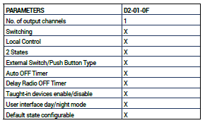
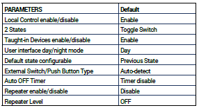
DEFAULT PAREMETERS
Parameters presentation
Switching: This option is to switch ON or OFF the Multifunction Relay Switch. If :
- Output value = (0x00) the Multifunction Relay Switch is switched OFF
- Output value from (0x01) to (0x64), the Multifunction Relay Switch is switched ON.
The Multifunction Relay Switch doesn’t have any dimming function.
Local control: This option is to activate or deactivate the local control of the Multifunction Relay Switch and on the wired switch connected. In both case, we can always access to the « Pairing mode » and « Factory Reset ».
Taught-in devices: If the parameter is activated, all the controllers paired to the Multifunction Relay Switch can control it. If the parameter is deactivated, only the home automation gateway can control the Multifunction Relay Switch.
User interface day/night mode: If the parameter is set to “Day”, the LED will be green when the Multifunction Relay Switch is Power On. If the parameter is set to “Night”, the LED will be OFF whatever the Multifunction Relay Switch is powered or not. Except for “Learning Mode” and “Reset” glowing. WARNING, once changed, this parameter does not allow anymore to see if the module is powered ON.
Default State: This parameter allows defining the state of the Multifunction Relay Switch after a power outage.
External Switch/Push Button Type: This option is to select the type of the wired switch (Mono-stable or bi-stable). By default
the Multifunction Relay Switch is configured to detect this mode by itself. Same option is applied for both wired switches.
Auto OFF Timer: When timer is activated with valid value (0.1 to 3600 sec), each time an output channel is set ON, it will be automatically set OFF when timer elapsed.
Delay Radio OFF Timer: When delay timer is activated with valid value (0.1 to 3600 sec), each time an output channel is set OFF by radio, it will be delay the action OFF of the time value choose.
Repeater enable/disable: When enable, the Multifunction Relay Switch can repeat a message not addressed to him, and increase range by creating network grid between all your EnOcean devices.
Local mode
The Multifunction Relay Switch can be switched ON or OFF locally, through a short press on the local button. This action will toggle both output at the same time.
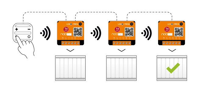
Advanced feature – repeater mode
The repeater mode has to be activated with the relay switch under power supply.
When the repeater mode is activated, the Multifunction Relay Switch will repeat all the messages from EnOcean network, and so increase the range of equipment around it.
The repeater mode has 3 levels:
- Level 0: repeater mode is deactivated
- Level 1: the signal is repeated (1 jump, see figure 1)
- Level 2: the signal is repeated (2 jumps, see figure 1)
Warning: by default during the first installation the repeater mode is at level 0.
Incrementation of the three levels for repeater mode:
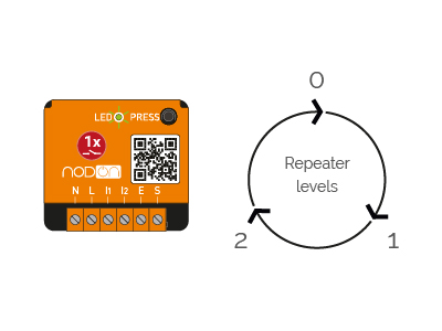
Working principle for repeater mode (figure 1):
Access to repeater’s next level:
Level 0 to level 1:
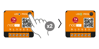
1 – Do 2 short presses.
2- The module LED blinks twice in green, confirming the activation of repeater’s next level.
Level 1 to level 2:
1 – Do 2 short presses.
2- The module LED blinks three times in green, confirming the activation of repeater’s next level.
Level 2 to level 0 (repeater mode is deactivated):
1 – Do 2 short presses.
2- The module LED blinks once in green, confirming the repeater’s mode deactivation.
Supported devices profiles
F6-02-01 – F6-04-01 – F6-10-00 – D5-00-01 – A5-07-01
A5-07-02 – A5-07-03 – A5-08-01 – A5-08-02 – A5-08-03
A5-10-19 – A5-10-18 – A5-10-1A – A5-10-1B – A5-10-1C
A5-10-1D – A5-10-01 – A5-10-05 – A5-10-08 – A5-10-0C
A5-10-10 – A5-10-13 – A5-10-16 – A5-10-17 – A5-10-0A
A5-10-0B – A5-14-01 – A5-14-02 – A5-14-03 – A5-14-04
Compatible smart home hub


Technical support
You have a specific question or need help regarding the installation or use of your product? Contact us by email at rf.no1714174289don@t1714174289roppu1714174289s1714174289 or at +33 7 68 04 20 90.